Here are the Code examples of this chapter. These pages are currently being updated over time (adding pictures, captions, and possibly further examples). Visit again soon for updates. Of course, the best way to use this page is together with the book for getting the explanations.

Figure 4.1 – A basic edge connecting two nodes
\documentclass[border=10pt]{standalone}
\usepackage{tikz}
\usetikzlibrary{positioning}
\begin{document}
\begin{tikzpicture}
  \node (tex) [fill=orange, text=white] {TEX};
  \node (pdf) [fill={rgb:red,244;green,15;blue,2},
    text=white, right=of tex] {PDF};
  \draw (tex) edge[->] (pdf);
\end{tikzpicture}
\end{document}

Figure 4.2 – An edge with a text label
\documentclass[border=10pt]{standalone}
\usepackage{tikz}
\usetikzlibrary{positioning}
\begin{document}
\begin{tikzpicture}
  \node (tex) [fill=orange, text=white] {TEX};
  \node (pdf) [fill={rgb:red,244;green,15;blue,2},
    text=white, right=of tex] {PDF};
  \draw (tex) edge[->] node[font=\tiny\ttfamily,above] {pdflatex} (pdf);
\end{tikzpicture}
\end{document}
With quotes syntax:
\documentclass[border=10pt]{standalone}
\usepackage{tikz}
\usetikzlibrary{positioning,quotes}
\begin{document}
\begin{tikzpicture}
  \node (tex) [fill=orange, text=white] {TEX};
  \node (pdf) [fill={rgb:red,244;green,15;blue,2},
    text=white, right=of tex] {PDF};
  \draw (tex)
    edge["pdflatex" {font=\ttfamily\tiny,above},->] (pdf);
\end{tikzpicture}
\end{document}
With style definitions:
\documentclass[border=10pt]{standalone}
\usepackage{tikz}
\usetikzlibrary{positioning,quotes}
\begin{document}
\begin{tikzpicture}[
    every node/.style={font=\large,text=white},
    every edge/.style={draw,->},
    every edge quotes/.style={auto,font=\ttfamily\tiny,text=black,fill=none}
  ]
  \node (tex) [fill=orange] {TEX};
  \node (pdf) [fill={rgb:red,244;green,15;blue,2},right=of tex] {PDF};
  \draw (tex) edge["pdflatex"] (pdf);
\end{tikzpicture}
\end{document}

Figure 4.3 – Four nodes
\documentclass[border=10pt]{standalone}
\usepackage{tikz}
\usetikzlibrary{positioning,quotes}
\begin{document}
\begin{tikzpicture}[
    every node/.style = {text=white, minimum width = 1.1cm},
    every edge/.style = {draw,->},
    every edge quotes/.style = {auto, font=\tiny\ttfamily, text=black}]
  ]
  \node (tex) [fill=orange] {TEX};
  \node (pdf) [fill={rgb:red,244;green,15;blue,2}, right = of tex] {PDF};
  \node (dvi) [fill=blue, above = of tex] {DVI};
  \node (ps)  [fill=black!60,above = of pdf] {PS};
\end{tikzpicture}
\end{document}
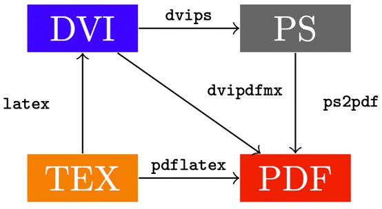
Figure 4.4 – Many edges with text
\documentclass[border=10pt]{standalone}
\usepackage{tikz}
\usetikzlibrary{positioning,quotes}
\begin{document}
\begin{tikzpicture}[
    every node/.style = {text=white, minimum width = 1.1cm},
    every edge/.style = {draw,->},
    every edge quotes/.style = {auto, font=\tiny\ttfamily, text=black}]
  ]
  \node (tex) [fill=orange] {TEX};
  \node (pdf) [fill={rgb:red,244;green,15;blue,2},right = of tex] {PDF};
  \node (dvi) [fill=blue, above = of tex] {DVI};
  \node (ps)  [fill=black!60, above = of pdf] {PS};
  \draw (tex) edge["pdflatex"] (pdf);
  \draw (tex) edge["latex"]    (dvi);
  \draw (dvi) edge["dvips"]    (ps);
  \draw (dvi) edge["dvipdfmx"] (pdf);
  \draw (ps)  edge["ps2pdf"]   (pdf);
\end{tikzpicture}
\end{document}
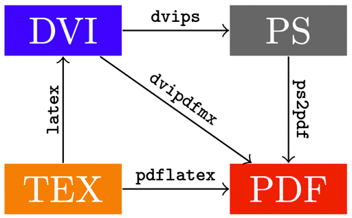
Figure 4.5 – Sloped text on edges
\documentclass[border=10pt]{standalone}
\usepackage{tikz}
\usetikzlibrary{positioning,quotes}
\begin{document}
\begin{tikzpicture}[
    every node/.style = {font=\large, text=white},
    every edge/.style = {draw, ->},
    every edge quotes/.style = {auto, font=\ttfamily\tiny,
      text=black, fill=none, sloped}]
  \node (tex) [fill = orange] {TEX};
  \node (pdf) [fill = {rgb:red,244;green,15;blue,2}, right = of tex] {PDF};
  \node (dvi) [fill = blue, above = of tex] {DVI};
  \node (ps)  [fill = black!60, above = of pdf] {PS};
  \draw (tex) edge["pdflatex"] (pdf);
  \draw (tex) edge["latex"]    (dvi);
  \draw (dvi) edge["dvips"]     (ps);
  \draw (ps)  edge["ps2pdf"]   (pdf);
  \draw (dvi) edge["dvipdfmx"] (pdf);
\end{tikzpicture}
\end{document}
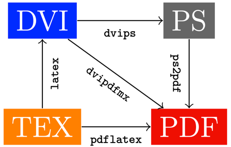
Figure 4.6 – Sloped text with the auto=right option
\documentclass[border=10pt]{standalone}
\usepackage{tikz}
\usetikzlibrary{positioning,quotes}
\begin{document}
\begin{tikzpicture}[
    every node/.style = {font=\large, text=white},
    every edge/.style = {draw, ->},
    every edge quotes/.style = {auto=right, font=\ttfamily\tiny,
      text=black, fill=none, sloped}]
  \node (tex) [fill = orange] {TEX};
  \node (pdf) [fill = {rgb:red,244;green,15;blue,2}, right = of tex] {PDF};
  \node (dvi) [fill = blue, above = of tex] {DVI};
  \node (ps)  [fill = black!60, above = of pdf] {PS};
  \draw (tex) edge["pdflatex"] (pdf);
  \draw (tex) edge["latex"]    (dvi);
  \draw (dvi) edge["dvips"]     (ps);
  \draw (ps)  edge["ps2pdf"]   (pdf);
  \draw (dvi) edge["dvipdfmx"] (pdf);
\end{tikzpicture}
\end{document}
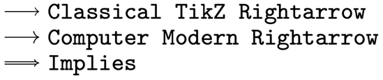
Figure 4.7 – Mathematical arrows
\documentclass[border=10pt]{standalone}
\usepackage{tikz}
\usetikzlibrary{arrows.meta}
\begin{document}
\begin{tikzpicture}[yscale=-1, y=2.5ex]
  \foreach \tip [count=\i] in {
    Classical TikZ Rightarrow, Computer Modern Rightarrow
  } {
    \draw [-{\tip}] (0, \i) to ++(0.5, 0)
      node [right] {\texttt{\tip}};
  }
  \draw [-{Implies}, double, yshift=2.2em] (0,1) to ++(0.5, 0)
    node [right] {\texttt{Implies}};
\end{tikzpicture}
\end{document}
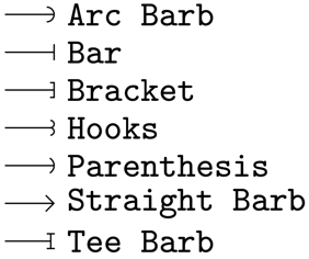
Figure 4.8 – Barbed arrows
\documentclass[border=10pt]{standalone}
\usepackage{tikz}
\usetikzlibrary{arrows.meta}
\begin{document}
\begin{tikzpicture}[yscale=-1, y=2.5ex]
  \foreach \tip [count=\i] in {
    Arc Barb, Bar, Bracket, Hooks, Parenthesis,
    Straight Barb, Tee Barb
  } {
    \draw [-{\tip}] (0, \i) to ++(0.5, 0)
      node [right] {\texttt{\tip}};
  }
\end{tikzpicture}
\end{document}
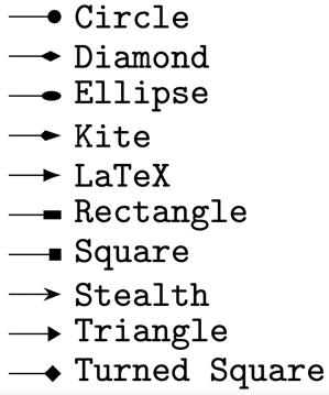
Figure 4.9 – Geometric arrows
\documentclass[border=10pt]{standalone}
\usepackage{tikz}
\usetikzlibrary{arrows.meta}
\begin{document}
\begin{tikzpicture}[yscale=-1, y=2.5ex]
  \foreach \tip [count=\i] in {
    Circle, Diamond, Ellipse, Kite, Latex, Latex[round],
    Rectangle, Square, Stealth, Stealth[round],
    Triangle, Turned Square
  } {
    \draw [-{\tip}] (0, \i) to ++(0.5, 0)
      node [right] {\texttt{\tip}};
  }
\end{tikzpicture}
\end{document}
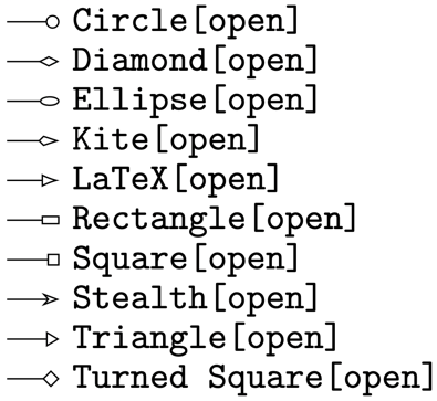
Figure 4.10 – Open geometric arrows
\documentclass[border=1pt]{standalone}
\usepackage{tikz}
\usetikzlibrary{arrows.meta}
\begin{document}
\begin{tikzpicture}[yscale=-1, y=2.5ex]
  \foreach \tip [count=\i] in {
    Circle[open], Diamond[open], Ellipse[open], Kite[open],
    Latex[open], Rectangle[open], Square[open], Stealth[open],
    Triangle[open], Turned Square[open]
  } {
    \draw [-{\tip}] (0, \i) to ++(0.5, 0)
      node [right] {\texttt{\tip}};
  }
\end{tikzpicture}
\end{document}

Figure 4.11 – A customized arrow tip
\documentclass[border=10pt]{standalone}
\usepackage{tikz}
\usetikzlibrary{positioning,arrows.meta}
\begin{document}
\begin{tikzpicture}
  \node (tex) [fill=orange, text=white] {TEX};
  \node (pdf) [fill={rgb:red,244;green,15;blue,2},
    text=white, right=of tex] {PDF};
  \draw (tex) edge[very thick, draw=red,
    -{Stealth[color=orange, fill=red, width=8pt, length=10pt]}]
    (pdf);
\end{tikzpicture}
\end{document}

Figure 4.12 – A curvy line with an arrow tip
\documentclass[border=10pt]{standalone}
\usepackage{tikz}
\usetikzlibrary{positioning}
\begin{document}
\begin{tikzpicture}
  \node (tex) [fill=orange, text=white] {TEX};
  \node (pdf) [fill={rgb:red,244;green,15;blue,2},
    text=white, right=of tex] {PDF};
  \draw[->] (tex) to[out=45, in=225, looseness=1.5] (pdf);
\end{tikzpicture}
\end{document}
Comparing –, to, and edge
\documentclass[border=10pt]{standalone}
\usepackage{tikz}
\usetikzlibrary{positioning}
\begin{document}
\begin{tikzpicture}
  \node (1) {1};
  \node (2) [right = of 1] {2};
  \node (3) [right = of 2] {3};
  \draw[->] (1) -- (2)
            (2) -- (3);
  \node (4) [below = of 1] {1};
  \node (5) [right = of 4] {2};
  \node (6) [right = of 5] {3};
  \draw [->] (4) to (5)
             (5) to (6);
  \node (7) [below = of 4] {1};
  \node (8) [right = of 7] {2};
  \node (9) [right = of 8] {3};
  \draw[->, color=red, very thick] (7) edge (8)
            (8) edge (9);
\end{tikzpicture}
\end{document}
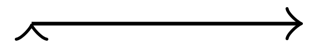
Figure 4.13 – An undesired arrow tip
Comment:
We use the arrow as edge option, because the edge operation
creates a separate path. It inherits the arrow though. But see what happens here:
\documentclass[tikz,border=10pt]{standalone}
\begin{document}
\begin{tikzpicture}
  \draw[->]  (0,0) edge (1,0);
\end{tikzpicture}
\end{document}
We have an undesired arrow at the beginning of the path.
Please rate (and possibly review) the book on Amazon if you got it there, your feedback means much to me and helps to get an extended second edition!
Go to next chapter.